
Revise
Capacitance
Capacitance
A capacitor is an electrical component which is capable of storing and releasing energy. The capacitor is capable of storing energy before releasing the energy to supply another component or device.
Capacitance
Each capacitor has a capacitance which represents the amount of energy the capacitor can store. The greater the capacitance of a capacitor, the more energy the capacitor can store when fully charged.
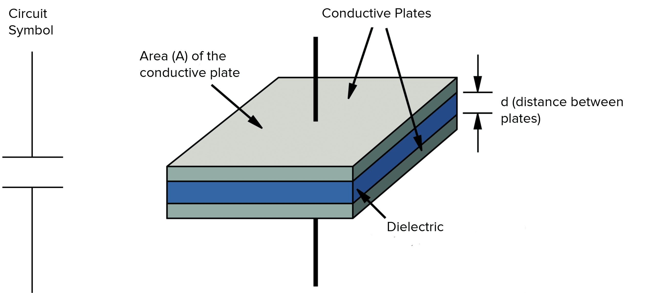
The most common type of capacitor is the parallel plate capacitor shown below. This diagram also shows the circuit symbol for the capacitor. Capacitance is measured with the units Farads, although many capacitors will have a capacitance stated in microFarads \left( \mu \text{F}\right) or nanoFarads \left(\text{nF}\right):
- 1 \: \mu \text{F} = 1 \times 10^{-6} \: \text{F}
- 1 \: \text{nF} = 1 \times 10^{-9} \: \text{F}
Capacitance is the amount of charge stored per unit of potential difference, giving the equation:
C = \dfrac{Q}{V}
- C is the capacitance in Farads \left(\text{F}\right).
- Q is the amount of charge stored in the capacitor in coulombs \left(\text{C}\right).
- V is the potential difference across the plates of the capacitor \left(\text{V}\right).
Example: A parallel plate capacitor has a capacitance of 2.5 \: \text{nF}. The capacitor is connected to a 500 \: \text{V} power supply. What is the charge on the plates of the capacitor?
[2 marks]
C = \dfrac{Q}{V} rearranges to Q = CV
Q = 2.5 \times 10^{-9} \times 500
Q = 1.25 \times 10^{-6} \: \text{or} \: 1.25 \: \mu \text{C}
Capacitance may also be calculated using the equation:
C = \dfrac{A \epsilon_0 \epsilon_r}{d}
- C is the capacitance of the capacitor in Farads \left(\text{F}\right).
- A is the area of the plates of the capacitor in metres squared \left(\text{m}^2\right).
- \epsilon_0 is the permittivity of free space \left(8.85 \times 10^{-12} \: \text{Fm}^{-1}\right).
- \epsilon_r is the relative permittivity in Farads per metre \left(\text{Fm}^{-1}\right).
- d is the separation between the plates of the capacitor in metres \left(\text{m}\right).


AQA A Level Physics Predicted Papers 2026
Our A Level Physics Predicted Papers are produced to the same high standard as real examination papers. Every question is written and reviewed by Physics subject specialists to ensure the level of challenge, format and structure closely reflect genuine A Level Physics exams. Each pack includes professionally printed exam papers and physical mark schemes, providing students with a realistic exam-style experience that goes beyond PDFs or generic revision materials. Checkout below and receive exclusive predicted papers available only from MME.
View Product
Parallel Plate Capacitors
As seen in the previous diagram, most capacitors make use of a dielectric material. A dielectric material is made of polar molecules.
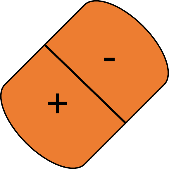
A single dielectric/polar molecule has a positive pole and a negative pole as seen here.
When no charge is applied to the plates of the capacitor, the dielectric molecules are free to be in any position and direction. Therefore, the dielectric molecules in a material will not be aligned but will be pointing in random directions.
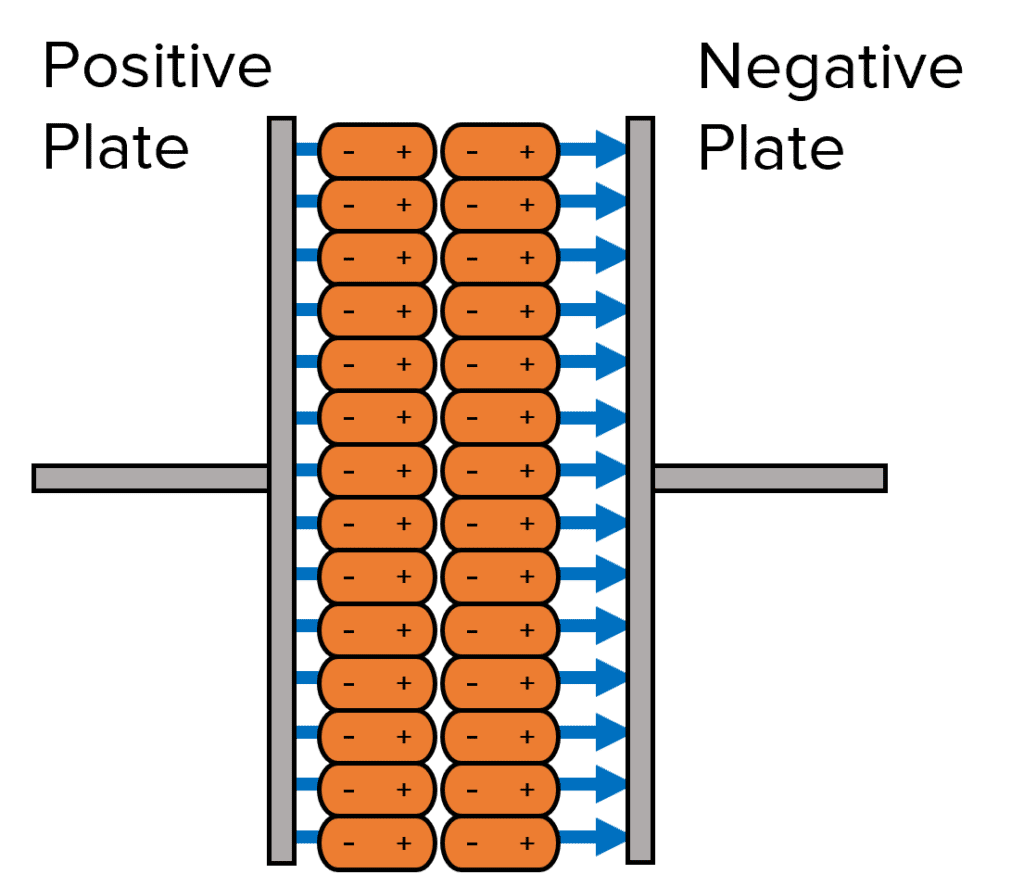
However, when a charge is put across the parallel plates, each plate takes on an opposite charge and all the dielectric molecules align accordingly. This is because the positive pole is attracted to negative plate and the negative pole is attracted to the positive plate.
The dielectric material has a relative permittivity. The permittivity of a material quantifies how easy it is for the material to generate an electric field.
The relative permittivity \left(\epsilon_r\right) of a material (also known as the dielectric constant) is given by the equation:
\epsilon_r = \dfrac{\epsilon}{\epsilon_0}
where \epsilon_r is the relative permittivity, \epsilon is the permittivity of the material you are measuring and \epsilon_0 is the permittivity of free space \left(8.85 \times 10^{-12}\right). All are measured in \text{Fm}^{-1}.
Example: Calculate the permittivity of a material with a relative permittivity of 9 \times 10^{10}.
[2 marks]
\epsilon_r = \dfrac{\epsilon}{\epsilon_0}
\epsilon = \epsilon_r \times \epsilon_0
\epsilon = 9 \times 10^{10} \times 8.85 \times 10^{-12}
\epsilon = 0.80 \: \text{Fm}^{-1}
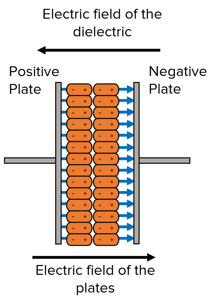
When a charge is passed through to the plates of the capacitor, an electric field is produced between the plates. At the same time, the dielectric molecules align themselves and create their own electric field. From the diagram below, we can see that when this occurs, the electric fields oppose each other.
The better the dielectric molecules align, the greater the opposing electric field would be and the larger the permittivity of the dielectric material. This consequently causes a decrease in the potential difference between the plates and increases the capacitance.
Capacitance Example Questions
Question 1: A parallel plate capacitor has a capacitance of 10 \: \text{nF}. The capacitor is connected to a 250 \: \text{V} power supply. What is the charge on the plates of the capacitor?
[2 marks]

Question 2: What is meant by the permittivity of a material?
[1 mark]
A quantity which determines how easy it is for an electric field to be produced in the material.
Question 3: Water has a relative permittivity of 78.4. Calculate the permittivity of water.
[2 marks]
Specification Points Covered
AQA A Level:
- 3.7.4.1 Capacitance (A-level only)
- 3.7.4.2 Parallel plate capacitor (A-level only)
Capacitance Worksheet and Example Questions
Capacitor Questions
A LevelOfficial MME