Resistors
Resistors Revision
Resistors
Resistors are circuit components that provide a given resistance to a circuit. They can be used to change the properties of a circuit. Other circuit components such as lamps and diodes also have the property of resistance.
Types of Resistors
The I-V graph for a resistor can be used to compare different resistors. In an I-V graph, the current is on the y-axis and the potential difference is on the x-axis. The gradient of the graph represents the resistance which can be calculated at any point on the graph by reading the the potential difference and current at that point an calculating the resistance using:
\text{R}=\dfrac{\text{V}}{\text{I}}
- R = resistance in ohms (\Omega)
- V = potential difference in volts \text{(V)}
- I = current in amps \text{(A)}.
Different types of resistors and components have different characteristic I-V graphs. The three main types of resistors are:
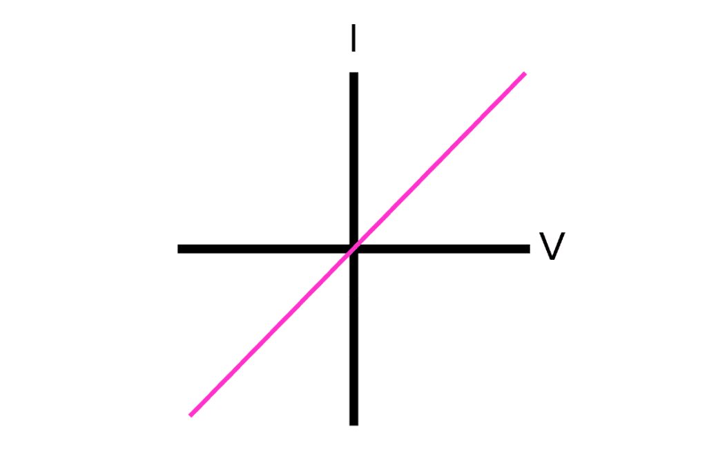
Ohmic Resistors:
If the current and potential difference are directly proportional (a straight line through the origin) the resistor is said to be ohmic.
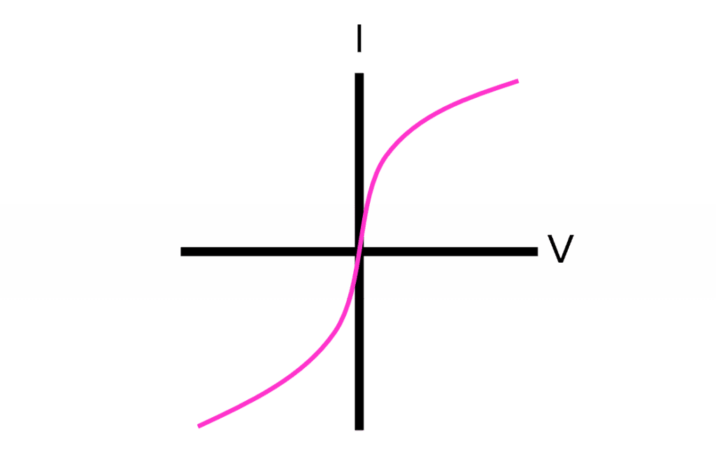
Non-ohmic Resistors:
The resistance of some resistors and other circuit components such as lamps change depending on the current across the resistor or component. This is because when the current increases, the wire gets hot and the metal atoms in the wire vibrate, causing more resistance. Such components are called non-ohmic.
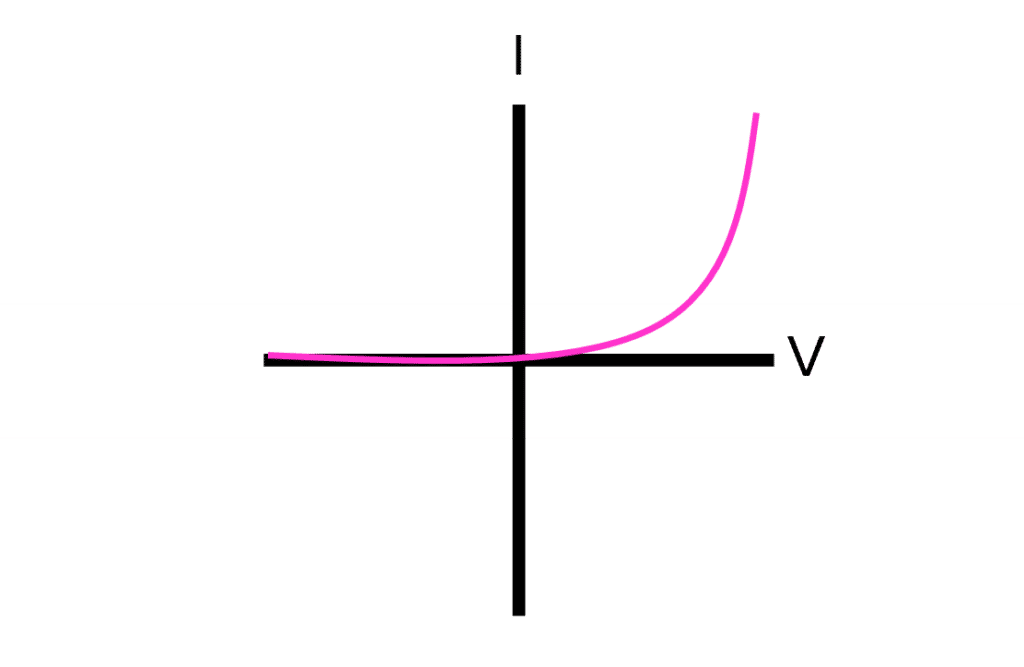
Diodes:
Diodes allow current to flow one direction only and only when the potential difference has reached a threshold voltage. Above the threshold voltage the resistance drops rapidly and the current increases rapidly. In the direction opposite to the allowed flow through the diode, resistance remains very high for all values of potential difference.
Sensing Circuits
There are some types of resistor that are designed to respond differently to current and potential difference.
A thermistor is designed so that the resistance decreases as the temperature increases.
A LDR (light dependent resistor) is designed so that resistance decreases as the light intensity upon the LDR increases.
These components can be used in sensing circuits. These are a type of circuit where a thermistor or LDR is used to vary the resistance across another component, so that the current across the component increases under certain conditions. For example, a thermistor may be used in a sensing circuit to switch on a heater only when it is cold or to switch on a fan when it gets hot.
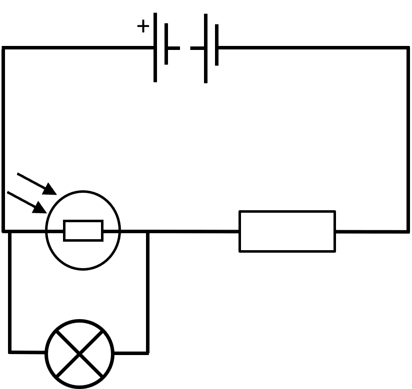
A different example of a sensing circuit is shown on the left. This circuit is designed so that when the classroom gets dark, the bulb switches on.
In this example, the bulb shares the potential difference with the LDR depending on the resistance of the LDR.
When the classroom is dark, the resistance of the LDR is large. Therefore both the LDR and the bulb will have a high pd. This means the bulb gets more energy and hence it is brighter in darker rooms.
When there is bright light in the classroom, the LDR has a very low resistance. The bulb will also have a very low resistance and hence it will be dimmer due to a lower pd.
Required Practical
Investigating I-V Characteristics
You have learned the three types of resistors, now you can investigate circuit components and identify which components act as which type of resistor.
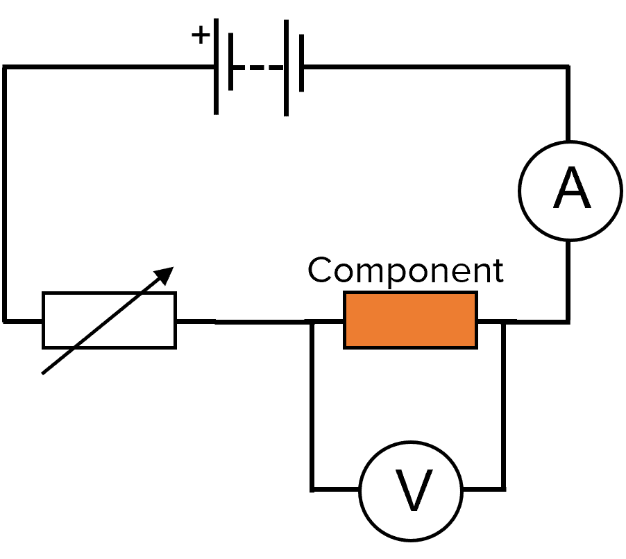
Doing the experiment
- Set up the circuit as shown in the diagram. Use a filament lamp, a diode or a resistor at a fixed temperature as the component.
- Use the variable resistor to change the current through the circuit. For each current, record the current and potential difference.
- Swap over the wires to the battery and repeat this experiment again. The ammeter will display a negative current and because the potential difference is in the opposite direction, you should record it as a negative value.
- Repeat the experiment with your other components.
- Plot an I-V graph for each of the components and identify which type of resistor they are: are they ohmic, non-ohmic or a diode?
Resistors Example Questions
Question 1: Sketch the I-V graph of an ohmic resistor.
[2 marks]
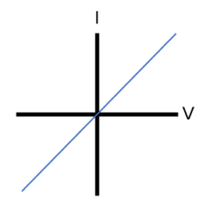
(1 mark for straight line sloping upwards, 1 mark for passing through the origin)
Question 2: Why does the resistance of a non-ohmic resistor increase with increasing temperature?
[1 mark]
Due to the increase in temperature, the atoms in the resistor vibrate more and this increases resistance.
Question 3: What happens to the resistance of an LDR when bright light is shone onto it?
[1 mark]
The resistance decreases.
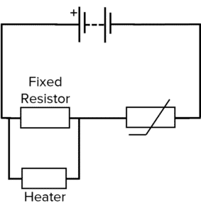
Question 4: Explain how the following circuit switches on a heater when it gets cold.
[4 marks]
When it is hot, the thermistor has low resistance and so the fixed resistor only has a small share of the potential difference. The heater has the same potential difference as the fixed resistor and so it does not switch on.
When it gets cold, the resistance of the thermistor increases. Now, the fixed resistor has a much greater share of the potential difference and so the heater is switched on.
Question 5: Describe an experiment you can use to determine the I-V characteristic of a filament bulb.
[6 marks]
Set up the circuit as shown in the diagram. Use the variable resistor to change the current through the circuit. For each current, record the current and potential difference. Swap over the wires to battery and repeat this experiment again. The ammeter will display a negative current and because the potential difference is in the opposite direction, you should record it as a negative value. Plot an I-V graph of the results. 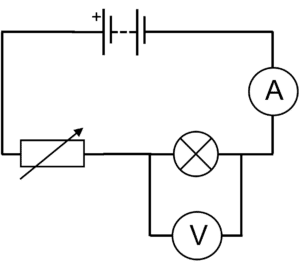

MME Premium Membership
£19.99
/monthLearn an entire GCSE course for maths, English and science on the most comprehensive online learning platform. With revision explainer videos & notes, practice questions, topic tests and full mock exams for each topic on every course, it’s easy to Learn and Revise with the MME Learning Portal.
Sign Up Now


