
Revise
Potential Divider Circuits
Potential Divider Circuits
A potential divider circuit is a series of resistors connected to a fixed power supply which is capable of splitting the input voltage into a fraction of the voltage. This is particularly useful for circuits where the power input is needed to supply several components with different potential differences.
Potential Dividers with Fixed Resistors
A potential divider circuit can be seen below. This circuit is made of a power source Vin and two fixed resistors. It also has a power output across R_1.

The potential divider circuit works by splitting the input voltages between the two resistors in a ratio of their resistances. For example, if both resistors were the same value for resistance, each would get half of the share of the input voltage.
An equation can be used to calculate the output voltage in circuits like the one above. This is not on your data sheet so worth noting and remembering:
V_{\text{out}}=\dfrac{R_1}{R_t}\times V_{\text{in}}
The equation can be adjusted so that the top value for resistance is the resistor of which the output voltage is over.
Example: Calculate the voltage output across the 200 \Omega resistor.
[2 marks]

\begin{aligned} \bold{V}_{\textbf{out}} &= \bold{\dfrac{R_1}{R_2} \times V}_{\text{in}} \\ &= \dfrac{200}{200+700} \times 6 \\ &= \bold{1.33} \textbf{ V} \end{aligned}
We can do a quick logical check of this. The smaller resistor will always receive the smallest share of the input voltage. So our answer looks good as R_1 is much smaller than R_2 so will only receive a small share of the input voltage.

AQA A Level Physics Predicted Papers 2026
Our A Level Physics Predicted Papers are produced to the same high standard as real examination papers. Every question is written and reviewed by Physics subject specialists to ensure the level of challenge, format and structure closely reflect genuine A Level Physics exams. Each pack includes professionally printed exam papers and physical mark schemes, providing students with a realistic exam-style experience that goes beyond PDFs or generic revision materials. Checkout below and receive exclusive predicted papers available only from MME.
View Product
Variable Resistors
For the output of a potential divider circuit to be variable, variable resistors, LDRs and thermistors may be included in the circuit. This is particularly useful if you want the circuit to control an outcome such as a light switching on or a fan switching on.

The circuit above includes a thermistor. Remember, a thermistor is a variable resistor whose resistance depends upon the temperature. As the temperature increases, the resistance decreases.
Example: In this potential divider circuit, what would happen to R_1, R_2 and V_{\text{out}} as the temperature of the thermistor increases?
[3 marks]
Firstly, as the temperature increases, \bold{R_2} decreases.
As R_1 is a fixed resistor, its resistance remains the same.
Finally, as R_2 has decreased, R_1 is now a larger part of the ratio of resistances and will therefore, receive a larger proportion of the input voltage. So \bold{V}_{\textbf{out}} increases.
Potential Divider Circuits Example Questions
Question 1: What is the purpose of a potential divider circuit?
[2 marks]
A Potential divider circuit is used to divide the input voltage in a circuit into smaller fractions of the voltage. This may be to supply multiple components that require a smaller voltage than the input voltage.

Question 2: Calculate the output voltage in this potential divider circuit.
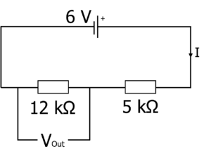 [2 marks]
Question 3: The potential divider circuit is used in a room which varies in temperature between 25 \degree C and 50 \degree C. At 25 \degree C, the resistance of the thermistor is 10 \text{ k} \Omega which decreases to 800 \, \Omega at 50 \degree C. What is the minimum and maximum output voltage from this circuit?
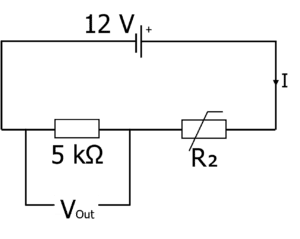 [3 marks]
At 25 \degree C:
\begin{aligned} \bold{ V}_{\textbf{out}} &= \bold{\dfrac{R_1}{R_2} \times V}_{\textbf{in}} \\ &= \dfrac{5 \times 10^3}{10 \times 10^3 + 5 \times 10^3} \times 12 \\ &= \bold{4} \textbf{ V}\end{aligned}
At 50 \degree C:
\begin{aligned}V_{\text{out}} &= \dfrac{R_1}{R_2} \times V_{\text{in}} \\ &= \dfrac{5000}{800+5000} \times 12 \\ =& \bold{10.3} \textbf{ V} \end{aligned}Therefore the minimum output voltage is 4 \text{ V} at 25 \degree C and the maximum output voltage is 10.3 \text{ V} at 50 \degree C.
Specification Points Covered
AQA A-level:
- 3.5.1.5 Potential divider