
Revise
Magnetic Flux Density
Magnetic Flux Density
Motors and generators are extremely useful in everyday appliances. These work based on the interaction of magnetic fields. To fully explain how motors and generators work, we need to begin by understanding the concept of magnetic flux density.
Magnetic Fields
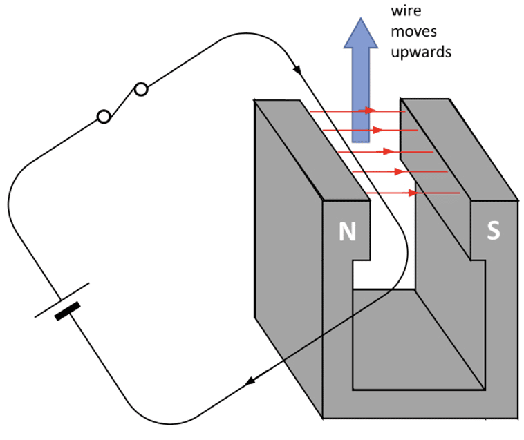
Any current-carrying conductor produces a magnetic field around it. If the magnetic field of the wire interacts with another magnetic field, a force will be exerted on the wire.
In the diagram on the right, a current carrying wire is being passed through a magnetic field. As the magnetic field of the wire interacts with the magnetic field of the magnets, a force is exerted on the wire. This force causes the wire to move if it’s not held in place.
The force applied to the current-carrying wire is determined by the equation:
F = BIL
- F is the force on the wire in Newtons \left(\text{N}\right).
- B is the magnetic flux density in tesla \left(\text{T}\right).
- I is the current in amps \left(\text{A}\right).
- L is the length of the wire in metres\left(\text{m}\right).
It is important for the above equation to work that the current carrying wire and the magnetic field of the magnet are perpendicular to each-other.
If not, the equation can be adapted to:
F = BIL \sin \theta
- \theta is the angle between the wire and the magnetic field lines of the magnets.
Therefore, if the current-carrying wire and the magnetic field are parallel \left(\theta = 0 \degree\right), \sin \theta would equal zero and no force would be produced.
Example: A current of 2 \: \text{A} flows through a wire perpendicular to a magnetic field of flux density \left(B\right) 100 \: \text{mT}. The length of the wire is 0.5 \: \text{m}. What is the magnitude of force on the wire?
[2 marks]
Because the wire is perpendicular to the field, \sin \theta = \sin 90 = 1 .
F = BIL
F = 100 \times 10^{-3} \times 2 \times 0.5
F = 100 \times 10^{-3} \: \text{N}


AQA A Level Physics Predicted Papers 2026
Our A Level Physics Predicted Papers are produced to the same high standard as real examination papers. Every question is written and reviewed by Physics subject specialists to ensure the level of challenge, format and structure closely reflect genuine A Level Physics exams. Each pack includes professionally printed exam papers and physical mark schemes, providing students with a realistic exam-style experience that goes beyond PDFs or generic revision materials. Checkout below and receive exclusive predicted papers available only from MME.
View ProductFleming’s Left Hand Rule
Let’s take another look at the previous diagram:
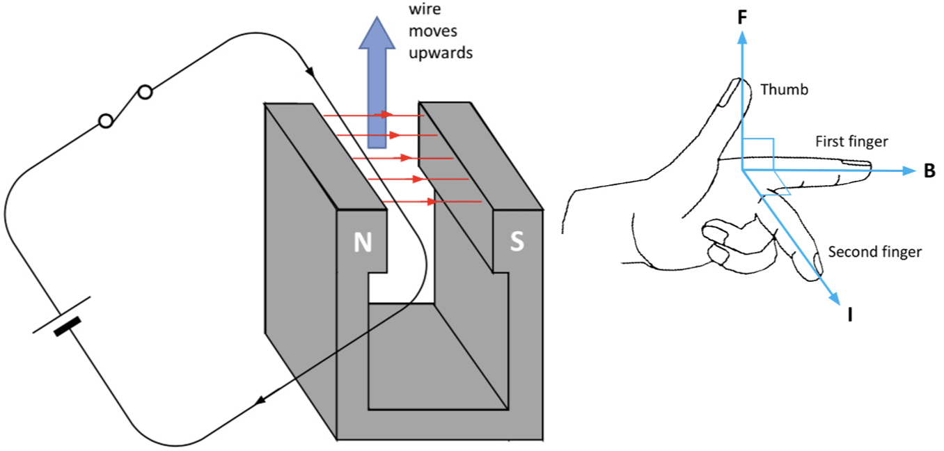
We can see that the direction of the force \left(F\right), current \left(I\right) and Magnetic Flux \left(B\right) have been labelled. Fleming’s left hand rule can be used to determine the direction of these variables. As the name suggests, it is important that the left hand is used and never the right.
Next to the diagram is a representation of Fleming’s left hand rule. The thumb represents the force or motion, the first finger is the direction of the magnetic flux and the second finger represents the current in the wire. As long as two of the directions are known, the third can be found by rotating the left hand to match the directions of the two variables known.

Magnetic Flux Density
The magnetic flux density is the strength of the magnetic field and is measured in Tesla’s. It can be defined as the magnitude of force acting on a current-carrying wire per unit of current per unit of length when the wire is placed within a magnetic field. This gives the following equation, which is just a rearranged version of the equation above:
B = \dfrac{F}{IL}
For this equation to be applicable, the magnetic field must be perpendicular to the wire. Magnetic flux density is given the unit Tesla \left(\text{T}\right) where 1 Tesla is equal to 1 Newton of force acting on a wire of 1 \: \text{m} in length with 1 \: \text{A} passing through it.
Example: A 32 \: \text{cm} length of wire is placed perpendicular to a magnetic field. Calculate the flux density when a current of 5 \: \text{A} flows through the wire, producing a force of 0.1 \: \text{N}.
[2 marks]
B = \dfrac{F}{IL}
B = \dfrac{0.1}{\left(5 \times 32 \times 10^{-2}\right)}
B = 0.063 \: \text{T}
Required Practical 10
Investigating how force varies with current through a wire in a magnetic field.
This experiment will use the following set up to observe how changing the current through a wire in a magnetic field will effect the force on this wire.
A similar experiment can be conducted where instead of the current through the wire being changed, the length of wire or strength of magnetic field is changed.
Doing the experiment:
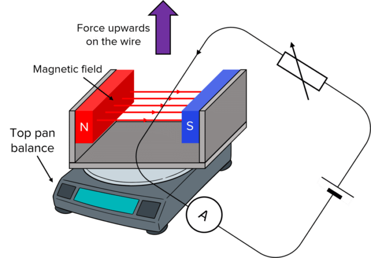
- Set up the experiment as shown above, with the power supply initially switched off. Place the magnet on a top pan balance. Reset the top pan balance to 0.0 \: \text{g}. Also measure the length of wire.
- Ensure the wire is completely perpendicular to the magnets as this would influence the experiments result if not.
- Measure the length of the magnets as this will give us the length of wire \left(L\right) inside the magnetic field.
- Switch the power supply on and adjust the current to 0.5 \: \text{A} using the variable resistor.
- As a result of the current now flowing through the wire, an upwards force is exerted on the wire. Due to Newton’s 3rd Law, there is equal and opposite force exerted on the magnet by the current carrying wire. Therefore there is a reading on the top pan balance. Record this reading on the top pan balance.
- Repeat this method but each time increase the current in intervals of 0.5 \: \text{A}, up until an appropriate maximum current.
- Repeat the entire experiment for each current 3 times and take a mean average mass for each current.
Analysing the results:
As the force on a current carrying wire is given by the equation;
F = BIL
The top pan balance measures the mass pushing down upon it. We know that the corresponding force is the mass multiplied by the gravitational acceleration: F = mg.
Therefore we can rewrite the equation as:
mg = BIL
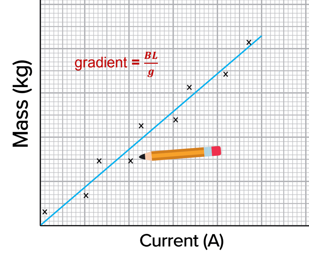
Plotting a graph of m against I would give a linear graph through the origin with a gradient equal to \dfrac{BL}{g}:
\begin{aligned} \textcolor{7cb447}{y} &= \textcolor{d11149}{m}\textcolor{2730e9}{x} \\ \textcolor{7cb447}{m} &= \textcolor{d11149}{\dfrac{BL}{g}}\textcolor{2730e9}{I}\end{aligned}
So in order to calculate the magnetic flux density we can use the equation:
\text{gradient} = \dfrac{BL}{g}
B = \dfrac{\text{gradient} \times g}{L}
Magnetic Flux Density Example Questions
Question 1: What is magnetic flux density?
[1 mark]
The strength of a magnetic field, often measured in tesla.

Question 2: What would the force on a current-carrying wire be if the wire and the magnetic fields are acting parallel to each other? Explain your answer.
[1 mark]
The force would be \boldsymbol{0} \: \textbf{N}, because \boldsymbol{\sin \theta = \sin 0 = 0} \: \textbf{N}. Therefore F = BIL \sin \theta = 0 \: \text{N}.
Question 3: A magnet produces a magnetic flux density of 5 \: \text{mT}. If 2 \: \text{m} of wire passes through the magnetic field carrying 3 \: \text{A}, what is the magnitude of force applied?
[2 marks]
Specification Points Covered
AQA A Level:
- 3.7.5.1 Magnetic flux density (A-level only)