
Revise
Current-voltage Characteristics
Current-voltage Characteristics
For the AQA course you are expected to describe Ohm’s Law and identify how it can be investigated. You are also expected to recognise and explain in detail the V-I graphs for ohmic conductors, filament bulbs and semiconductor diodes.
Ohm’s Law
Ohm’s law states “the current through a conductor is proportional to the potential difference across it”. This law only applies if the conductor is kept at a constant temperature as changes in temperature affects resistance. This law can be represented in the equation:
V=IR
- V= potential difference in volts \text{(V)}
- I= current in amperes \text{(A)}
- R= resistance in ohms (\Omega)
As a results, V \propto I when R is kept constant by maintaining a constant temperature.
A circuit just like the one below can be used to investigate Ohm’s law:

It is important to note that for a constant temperature to be maintained, the switch should only be closed for a very short period of time whilst measurements are being taken and then switched off. This is because the components of the circuit heat up while a current flows through them.
Using the circuit above, the variable resistor can be used to vary the current and potential difference. Pairs of readings for current and potential difference can be taken then resistance calculated using R=\dfrac{V}{I}.
For a component to obey Ohm’s law, when current is plotted against voltage, it should produce a linear graph through the origin similar to the one shown:

The resistance of the graph can be calculated by finding the inverse of the gradient.


AQA A Level Physics Predicted Papers 2026
Our A Level Physics Predicted Papers are produced to the same high standard as real examination papers. Every question is written and reviewed by Physics subject specialists to ensure the level of challenge, format and structure closely reflect genuine A Level Physics exams. Each pack includes professionally printed exam papers and physical mark schemes, providing students with a realistic exam-style experience that goes beyond PDFs or generic revision materials. Checkout below and receive exclusive predicted papers available only from MME.
View ProductI-V Graph for an Ohmic Conductor
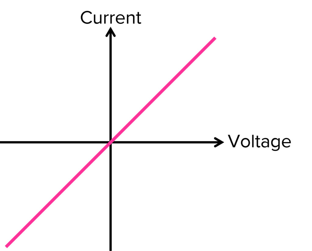
We have already seen the I-V graph for an Ohmic conductor such as a resistor at fixed temperature. The graph should look like the one below for an Ohmic conductor:
The graph shows the Ohmic conductor has a directly proportional relationship between current and potential difference. The resistance of the graph is given by \dfrac{1}{gradient}.

I-V Graph for a Filament Lamp (Non-ohmic)
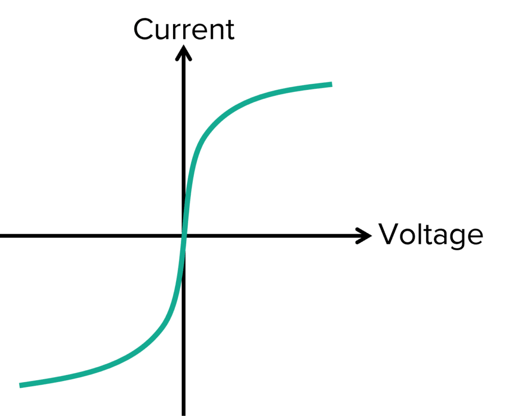
A filament lamp requires high temperatures to cause the filament inside the lamp to glow, producing light. The I-V graph is shown below:
The central part of the I-V graph for a filament lamp is linear, this only applies at very low potential difference. However, the graph then curves towards the axis for pd, indicating an increase in resistance (as a high increase in pd does not change current).
The change in resistance is caused by an increase in temperature. As the temperature of the filament lamp increases, its resistance also increases. As temperature increases, the particles in the filament vibrate more, increasing the resistance as the free electrons are more likely to collide with the atoms.
I-V Graph for a Semiconductor Diode
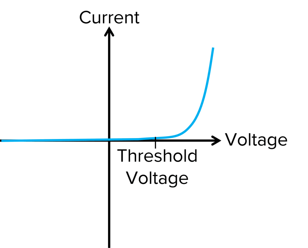
The I-V graph for a semiconductor diode is distinctive and looks very different from the previous two graphs. The shape of the graph is linked to the function of the diode. A diode is used in a circuit to prevent current flowing in the wrong direction around a circuit. The graph can be seen below:
For negative potential differences, zero current is able to flow. This is because a forward bias only allows current to pass through in the forwards direction.
At low positive potential differences, the semiconductor diode will not allow any current to pass through and therefore, the current remains zero.
At a specific potential difference, known as the threshold voltage, the diode rapidly allows large currents to pass through for small increases in potential difference. Most Silicon semiconductors have a threshold voltage of 0.7 \text{ V}.
Current-voltage Characteristics Example Questions
Question 1: Describe a method you could use to demonstrate that a fixed resistor obeys Ohm’s law.
[6 marks]
To demonstrate that a fixed resistor obeys ohm’s law, pairs of readings for current and voltage need to be taken. A series circuit containing a power source, variable resistor, fixed resistor, an ammeter in series and a voltmeter in parallel can be used. A pair of readings should be taken when the variable resistor is set to its minimum resistance. Then the variable resistor should be changed slightly and a new pair of readings taken. This should be repeated for at least 5 pairs of readings of V and I. Resistance can be calculated using \bold{V=IR}.
It is important to keep the temperature constant so the circuit needs to be switched on for as short a period of time as possible to prevent heating. A graph of V against I could be plotted. It should show a straight line through the origin as it obeys Ohms law.

Question 2: Describe and explain the I-V graph for a semiconductor diode.
[3 marks]
For negative potential differences, the current is zero as a diode only allows current to flow in the forward direction. At low positive potential differences, the current remains zero as it has not met the threshold voltage which is a certain minimum voltage needed for current to pass through a diode. Once the threshold voltage has been met, the current rapidly increases as resistance decreases.
Question 3: Describe why the shape for a filament bulb I-V graph is seen.
[2 marks]
At low potential differences in both directions, the filament bulb acts as an Ohmic conductor, hence the straight line through the origin. At higher potential differences, the graph curves as temperature and resistance increases.
Specification Points Covered
AQA A-level:
- 3.5.1.2 Current–voltage characteristics