
Revise
Basics of Electricity
Basics of Electricity
In this section we will begin to look at the topic of electricity. Many of these terms will be familiar to you from GCSE but you will require a more in-depth understanding for A-level.
Circuit Symbols
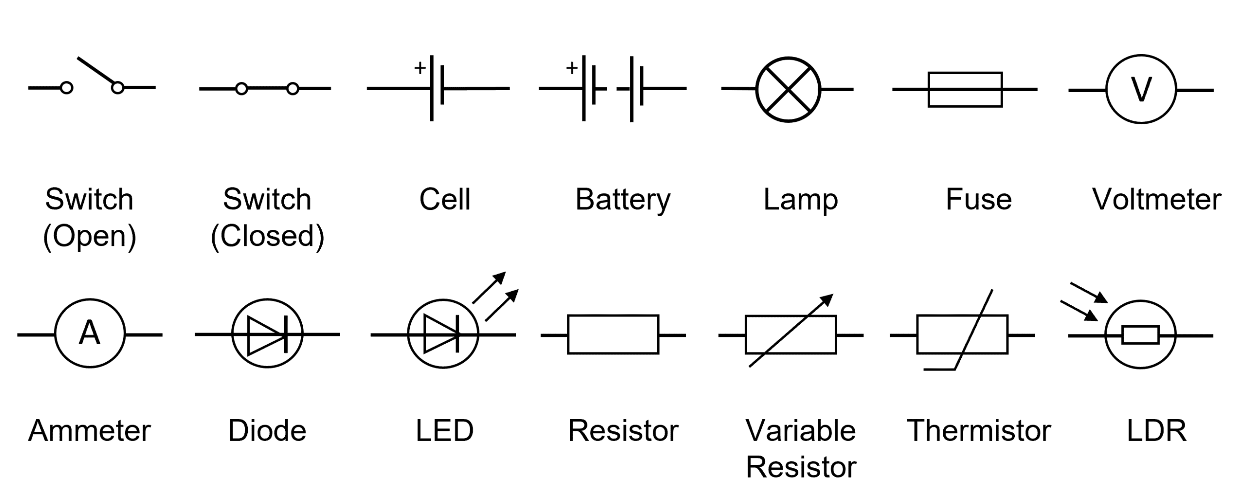
Circuits can be drawn using symbols to give a visual representation of what the desired circuit should include. Symbols allow scientists to visualise a circuit without a language barrier as symbols are universal. Here is some of the circuit symbols you will come across in this unit:
AQA A Level Physics Predicted Papers 2026
Our A Level Physics Predicted Papers are produced to the same high standard as real examination papers. Every question is written and reviewed by Physics subject specialists to ensure the level of challenge, format and structure closely reflect genuine A Level Physics exams. Each pack includes professionally printed exam papers and physical mark schemes, providing students with a realistic exam-style experience that goes beyond PDFs or generic revision materials. Checkout below and receive exclusive predicted papers available only from MME.
View ProductElectric Current
Electric current, which is measured in amperes \text{(A)} is defined as “the rate of flow of charge”.
As an equation, this can be written as:
I=\dfrac{\Delta Q}{\Delta t}
- I= current in amperes \text{(A)}
- \Delta Q= the charge in coulombs \text{(C)}
- \Delta t= the time in seconds \text{(s)}
Conventional current is defined as the flow of charge from the positive terminal to the negative terminal within a circuit. However, this definition was given before scientists had a full understanding of electricity and is actually opposite to the flow of electrons which flow from negative to positive.

To measure current, an ammeter is often used. For measuring very small currents, a microammeter may be used. These pieces of equipment can only work if they are inserted in series into a circuit.

Potential Difference
Potential difference (p.d) is defined as “the work done per unit of charge” and is measured in Volts \text{(V)}. This can be written as an equation in the form:
V=\dfrac{W}{Q}
- V= the potential difference in volts \text{(V)}
- W= work done in joules \text{(J)}
- Q= charge in coulombs \text{(C)}
The potential difference is a result of the power source which causes one end of the circuit to become positively charged, whilst the other end of the circuit becomes negatively charged.
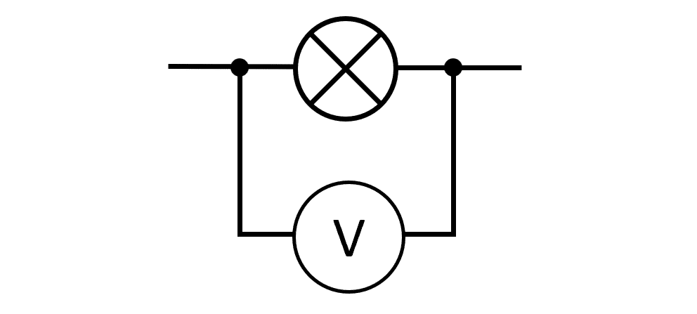
To measure potential difference, a voltmeter is used and should always be connected in parallel across the component needed to be measured. The terminal pd, which is the potential difference the circuit is supplied with, can be measured by putting the voltmeter in parallel across the terminals of the power source.
Resistance
Electrical resistance can be defined as “the opposition to motion of the charge carriers” or “the opposition to current”.
This can be written as an equation in the form:
R=\dfrac{V}{I}
- R= resistance in ohms (\Omega)
- V= potential difference in volts \text{(V)}
- I= current in amperes \text{(A)}
All components in a circuit have a resistance including the wires (in exam questions we considered the wires to have zero resistance) and these resistances contribute to the total resistance of the circuit. The amount of resistance determines how much current is able to pass through the circuit.
One Ohm (\Omega) can be defined as one volt per ampere (\text{VA}^-1) as an alternative unit.
Basics of Electricity Example Questions
Question 1: Give the definitions for current, potential difference and resistance.
[3 marks]
Current – the rate of flow of charge.
Potential Difference – the work done per unit of charge.
Resistance – the opposing force to current in a circuit.

Question 2: Give an alternative (non-SI) unit to the Ampere for current.
[1 mark]
I=\dfrac{Q}{t} so the alternative unit for current would be coulombs per second or \textbf{Cs}\bold{^{-1}}.
Question 3: Explain how you would measure the current, potential difference and resistance in a circuit.
[3 marks]
To measure current, an ammeter must be used in series.
To measure potential difference, a voltmeter must be used in parallel to the component you are trying to measure the potential difference of.
Resistance is not measured directly, it needs to be calculated using the equation \bold{R=\dfrac{V}{I}}.
Specification Points Covered
AQA A-level:
- 3.5.1.1 Basics of electricity